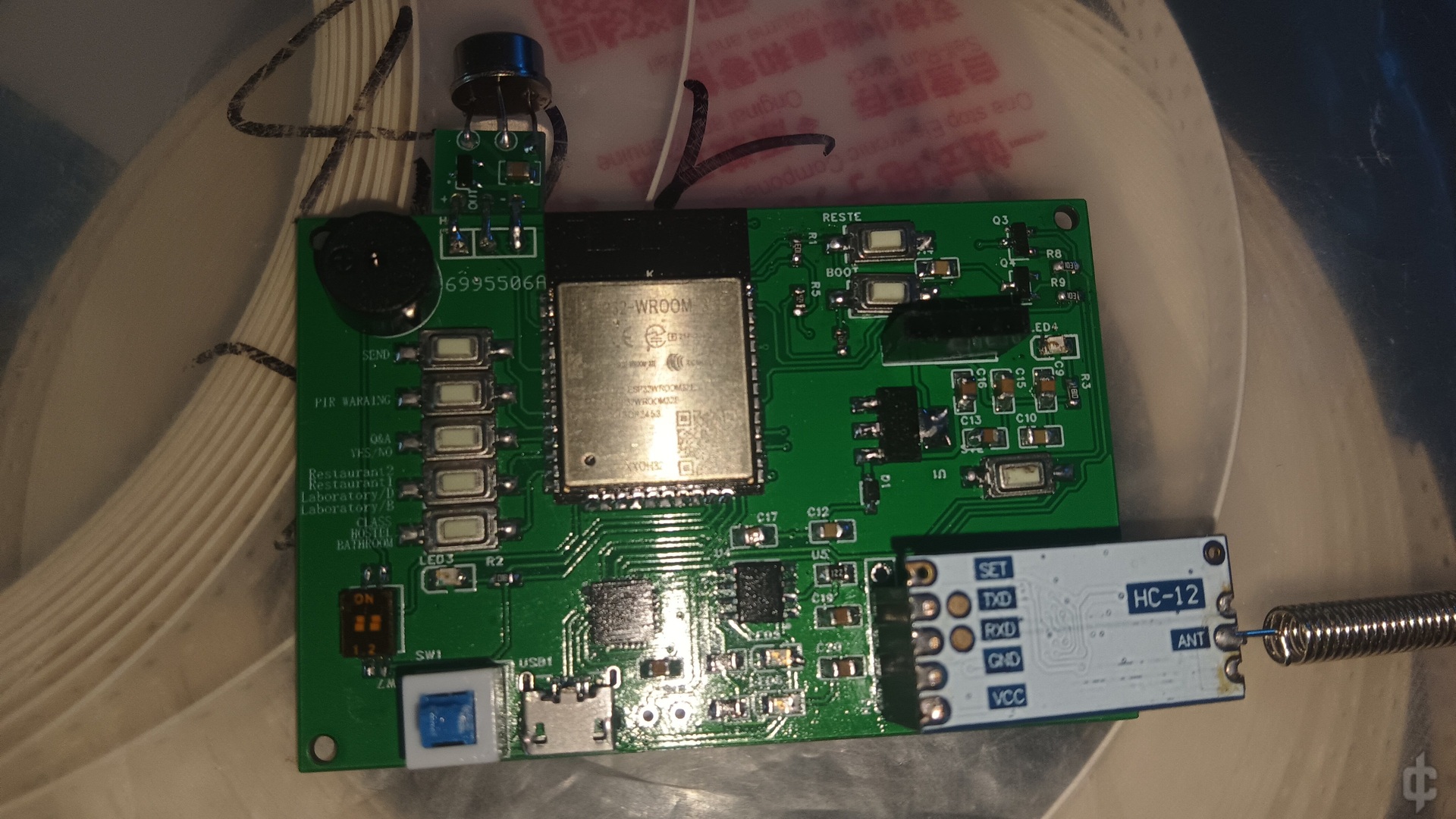
更正一下,按键以程序和pcb参考,上边位置改键位了
没有听错,就是二十年前的那个传呼机,现在已经基本消失了,不过因为我们学校占地面积比较大,加上不让用手机,地方比较多,放学了如果分开去吃个饭或者洗个澡之后根本就找不到人的尴尬,有时候找一个人还需要用最短路径,比如从教室到实验室到食堂到宿舍……,但是找半天也不知道去哪里了,于是复刻了一个类似功能的数字BP机,主控依旧是ESP32,用来收发的串口模块HC-12,因为活动范围直径不会超过二千米,加上手头正好有这个模块,放几个常见的命令来通讯,用OLED屏幕显示,比如所在的位置,问答的语句,发送按键,还增加了一个热释电的模块,有人体感应会给从机发送信息,免的你的室友在你不在宿舍的情况下对你的柜子或者行李箱里吃的进行零元购


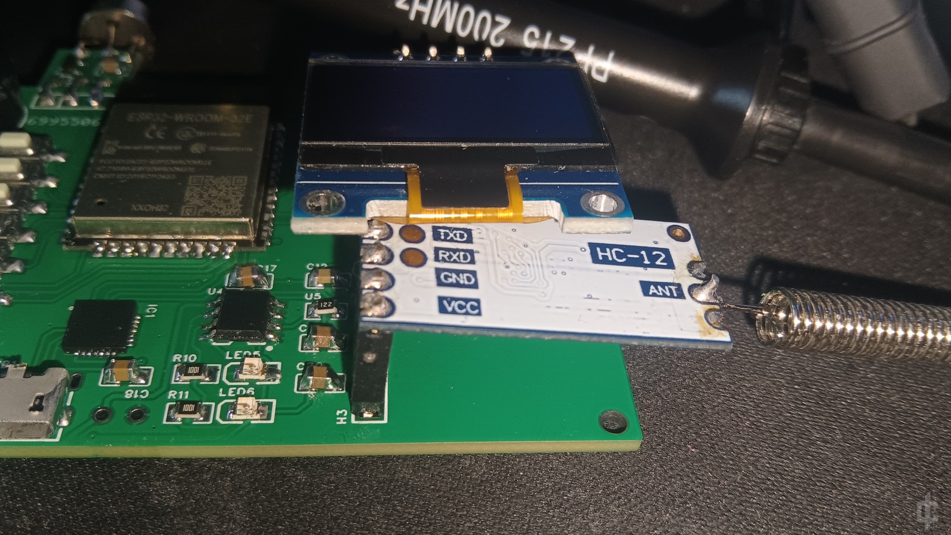
串口芯片用的是cp2104,附带了一个4056来给充电,就是串口模块和屏幕摆放不太合理,有点别扭
从左上角开始数的按键用处,第一个是发送按键,起到一个保险
作用,选中要发送的信息再按确保不会误触,第二个就是热释电感应,按一下启动,感应到有人靠近就会自动给从机发送信息,第三个是选择发送的按键,内置几个询问和回复的话
such: where are you,come to me ,ok,no,
i am busy ,wait to come
剩下的两个按钮就是位置了,可以根据自己需要更改代码比如我这个
1/Restaurant 2/Restaurant食堂
class hostel,1/laboratory,2labrotary实验室
我觉得英文比较方便改,多学几个单词也没有坏处(实际上是我懒得折腾字库)
剩下两个拨钮是控制蜂鸣器开关的,另一路可以增加点其他的功能
右上是ESP32的复位和Boot按键,下边的按键是调整串口模块的空中波特率和其他参数的
这里放一下micropython的代码
from machine import Pin, SoftI2C, UART
from ssd1306 import SSD1306_I2C
import time

# Initialize UART
uart = UART(2, 9600, rx=16, tx=17)

# Initialize pins connected to buttons
key1 = Pin(14, Pin.IN, Pin.PULL_UP)
key2 = Pin(27, Pin.IN, Pin.PULL_UP)
key3 = Pin(26, Pin.IN, Pin.PULL_UP)
key4 = Pin(25, Pin.IN, Pin.PULL_UP)

# Initialize PIR sensor and beep pin
pirPin = 34
beep_pin = Pin(15, Pin.OUT)
pir = Pin(pirPin, Pin.IN, Pin.PULL_DOWN)
pir_state = 0

# Initialize states
key1_states = [
    "1/Restaurant",
    "2/Restaurant",
    "Bathroom",
    "Hostel",
    "B/Laboratory",
    "D/Laboratory"
]
key2_states = [
    "Where are you?",
    "Come to me",
    "OK",
    "No",
    "I am busy",
    "Wait to come"
]
current_state_index_key1 = 0
current_state_index_key2 = 0
last_state = None
received_message = None
def key1_irq(pin):
    global current_state_index_key1, last_state
    if pin.value() == 0:
        current_state_index_key1 = (current_state_index_key1 + 1) % len(key1_states)
        last_state = key1_states[current_state_index_key1]
        display_text(sent_text=last_state)
def key2_irq(pin):
    global current_state_index_key2, last_state
    if pin.value() == 0:
        current_state_index_key2 = (current_state_index_key2 + 1) % len(key2_states)
        last_state = key2_states[current_state_index_key2]
        display_text(sent_text=last_state)
def key3_irq(pin):
    global last_state
    if pin.value() == 0:
        if last_state is not None:
            uart.write(last_state + "\n")
            print("Sent over UART:", last_state)
            display_text(sent_text=last_state)
def key4_irq(pin):
    global pir_state
    if pin.value() == 0:
        pir_state = not pir_state
        if pir_state:
            print("PIR sensor active")
        else:
            print("PIR sensor inactive")
def display_text(sent_text=None, received_text=None):
    oled.fill_rect(0, 20, 128, 16, 0)
    oled.fill_rect(0, 40, 128, 16, 0)
    if sent_text:
        oled.text("T:" + sent_text, 0, 20)
    if received_text:
        oled.text("R:" + received_text, 0, 40)
    oled.show()
def beep():
    beep_pin.value(1)
    time.sleep(0.1)
    beep_pin.value(0)
    time.sleep(0.1)
if __name__ == "__main__":
    i2c = SoftI2C(sda=Pin(23), scl=Pin(18))
    oled = SSD1306_I2C(128, 64, i2c)
    key1.irq(trigger=Pin.IRQ_FALLING, handler=key1_irq)
    key2.irq(trigger=Pin.IRQ_FALLING, handler=key2_irq)
    key3.irq(trigger=Pin.IRQ_FALLING, handler=key3_irq)
    key4.irq(trigger=Pin.IRQ_FALLING, handler=key4_irq)

    while True:
        if uart.any():
            received_message = uart.read().decode('utf-8').strip()
            print("Received over UART:", received_message)
            display_text(received_text=received_message)
            beep()
            uart.write(received_message + "\n")
            print("Echoed back over UART:", received_message)
        if pir_state and pir.value() == 1:
            oled.fill(0)
            oled.text("Someone", 0, 20)
            print('Detect someone...')
            beep()
        time.sleep(0.1)
效果视频
video_20240819_121613_edit.mp4 点击下载
PCB


工程文件
掉电运行把serial改成main
测试一下代码
PIR感应
video_20240819_122727.mp4 点击下载
按键发送
video_20240819_122802.mp4 点击下载
接收 hello world
video_20240819_122917.mp4 点击下载


200字以内,仅用于支线交流,主线讨论请采用回复功能。